Historical preservation of the Patinho Feio computer (USP - 1971)

The original thread was authored in Brazilian Portuguese and published (on December 26th, 2016) at:

This translation into English was contributed by my friend Seth Schoen. Thanks, Seth!
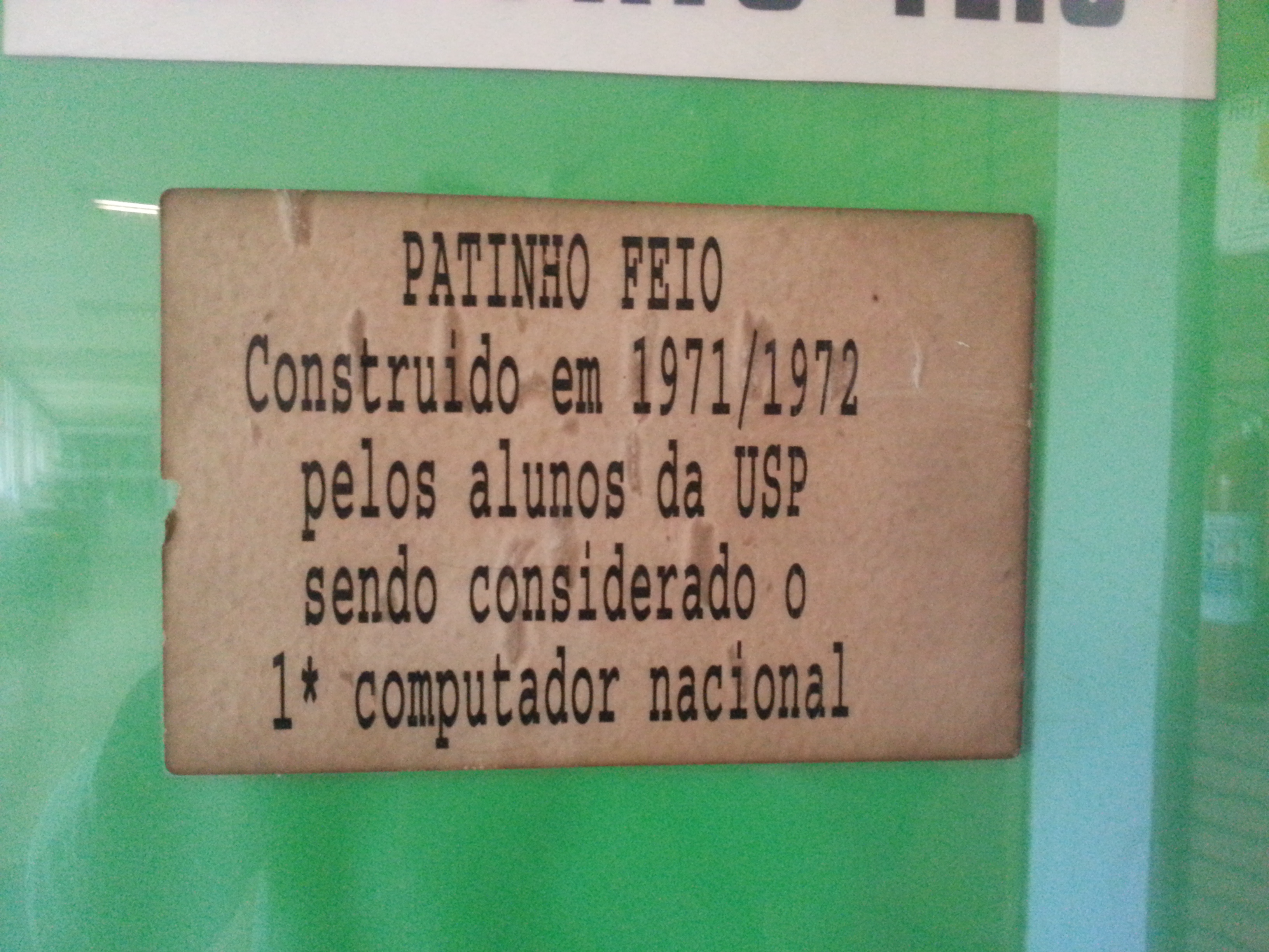
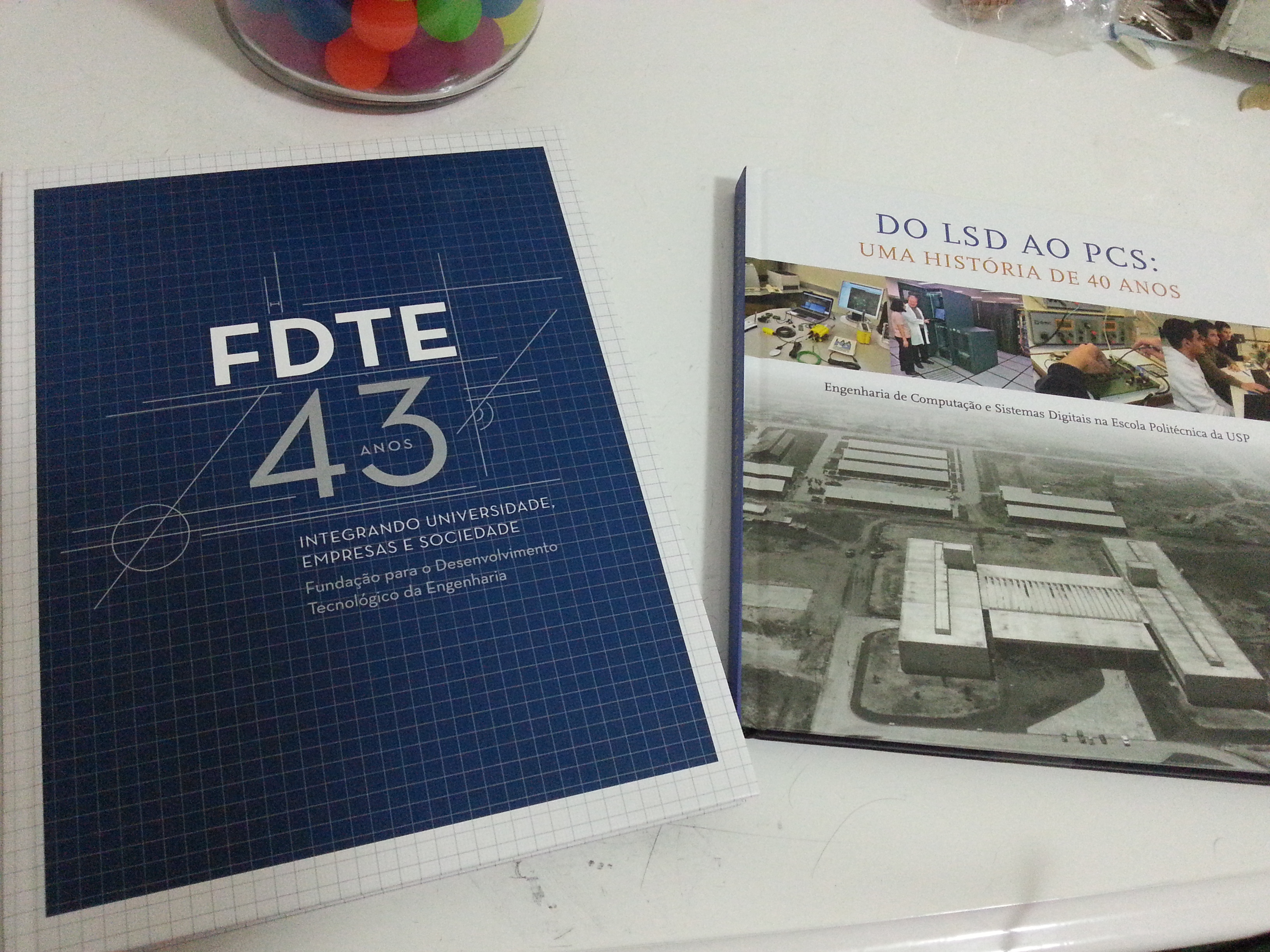
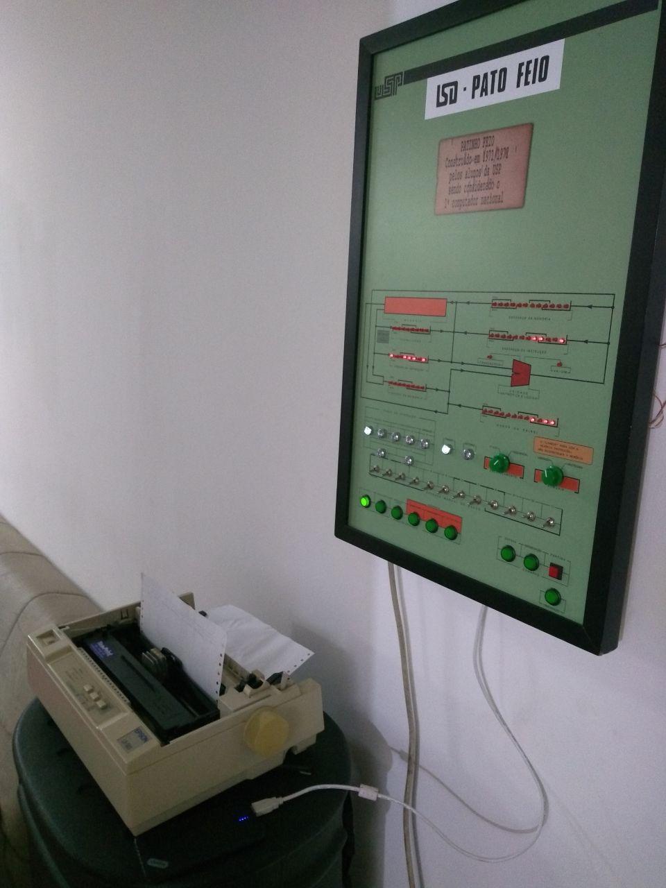

(PATINHO FEIO
Built in 1971/1972
by the students at USP
being considered the
1st Brazilian computer)

I’ve already told a little tiny bit of this story in a post on my blog (in English) at:

http://mamedev.emulab.it/fsanches/2015/11/18/a-pleasant-visit-to-the-university/9

But here I’m going to go into further detail and try to recount everything that’s happened up to now, and, maybe, updates on the project’s next steps. This project concerns the historic preservation of the Patinho Feio [Portuguese: ‘Ugly Duckling’] computer, which was designed at the University of São Paulo (USP) in 1971.

In November 2015, I was very interested in 3D scanning arcade game cabinets and video game consoles, and, as a result, I went to USP to try to speak to somebody from LSI (the USP Integrated Systems Laboratory) or Caverna Digital, in the hope of finding a 3D scanner. I didn’t manage to find Prof. Roseli de Deus Lopes (from LSI) on that trip, but I ended up meeting Prof. João José Neto.

In the course of my conversation with Prof. JJNeto, I mentioned that I’ve already worked for several years as a volunteer on initiatives for the historic preservation of computers and video games (and, in fact, all sorts of digital devices) by means of emulation and that, in support of this, I’ve contributed to emulator implementations for the MAME Project.

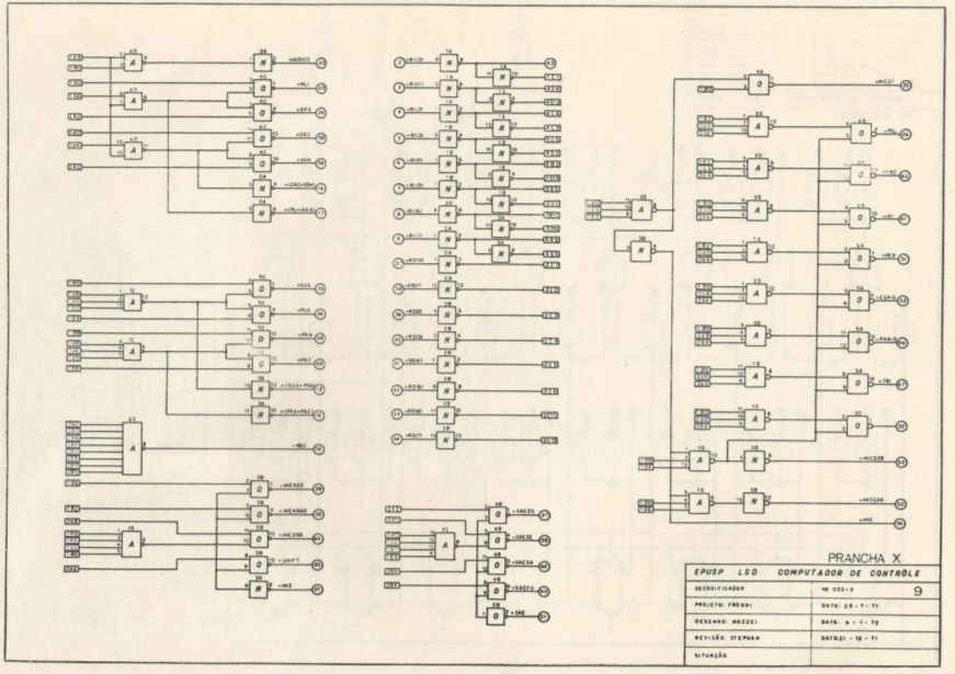
I ended up showing the professor some of my MAME drivers and he, in return, handed me a document from 1977 called “Assembler for Patinho Feio”. It’s a user manual for an assembler program for the machine language of the Patinho Feio CPU. Since supposedly no other copy of this work was known to exist, I grew quite worried, because it was a nearly 40-year-old document that had been extremely well preserved up to that point. And now this rare artifact was being placed in my clumsy hands…

I was terrified! I ran home, taking care to protect the document, and I started the process of digitizing it the moment I got to my house. Since it didn’t fit in my scanner (the pages were a tiny bit bigger than standard A4 size), I simply took photos of each page with my phone. I saved all the photos in high resolution in a GitHub repository and then I made a little script to scale and compress the pages and then combine them into a PDF with reasonable quality and size. The resulting PDF was published on the Internet Archive and can be found here:

Next, I read through the document carefully and observed that it would be possible to use the information it contained to implement an emulator for the Patinho Feio’s CPU. But in order to test the emulator, I would need access to programs written for the machine. And at that point the only thing I had access to was a little “Hello World” whose machine code was readable in the photograph of a little strip of punched paper tape that appeared in a picture in the book itself.

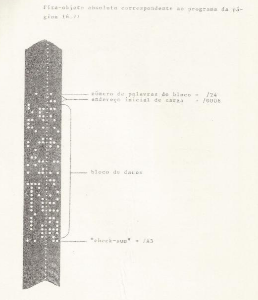
I manually transcribed each byte from the tape in the picture, producing a file that could be loaded into my emulator, and then used this program to debug my implementation. This way, I managed to make the tiny program work in the emulator and see characters displayed on my screen which originally were sent to the teletype - a writing machine with a serial interface to communicate with the computer. The characters were being sent gradually one by one: P - A - T - I - N - H - O - [space] - F - E - I - O followed by a linefeed command (to advance the paper by one line) and then a carriage return (to make the print head return to the left corner of the page).

Emulation of the “Hello World” program

Using a technology called emscripten, I compiled the MAME driver to Javascript, which allows the emulator to run directly in a web browser. At that point I set up a web page to host this demo. You can see it here:

http://felipesanches.github.io/emuladores/patinho.html

Sometime later, I went back to the USP Polytechnic along with Armando Neto (one of our friend from here on Fiozera!), and we took some photos of the actual computer, which is on display nowadays in the administration building of the Polytechnic Institute.

Based on these photos, I redrew the entire panel in Inkscape (a free software application for vector art), and, now that I had a vector file of the panel artwork, I started building a replica of the Patinho Feio, outsourcing the laser cutting and printing of a sticker of the art to a printing bureau near my house.

Below you can see the vectorization of the front panel art:

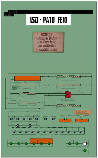
The corresponding vector file is available here.

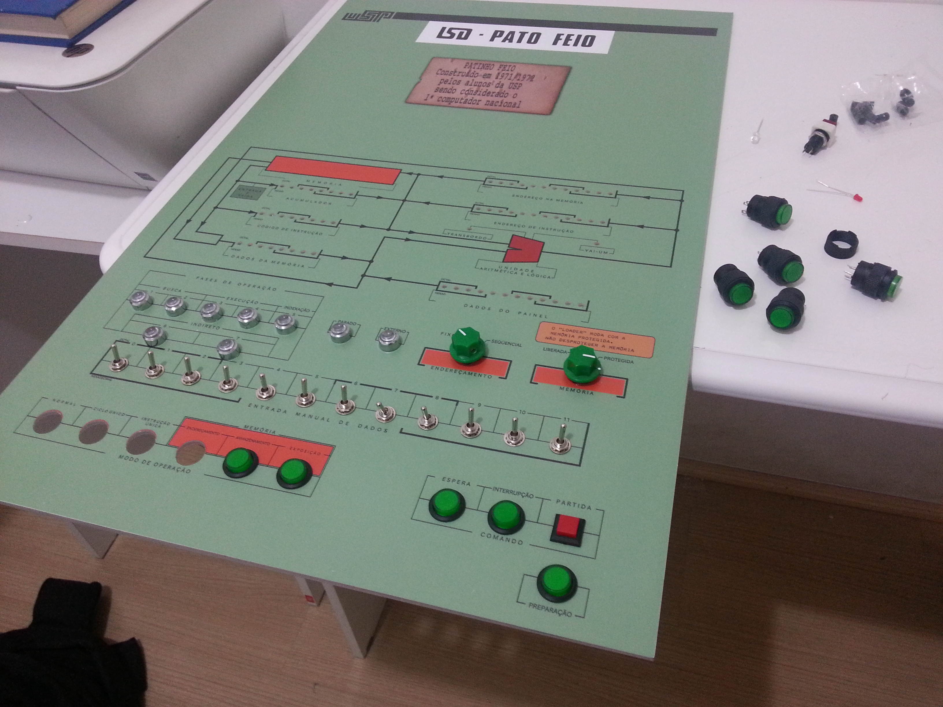
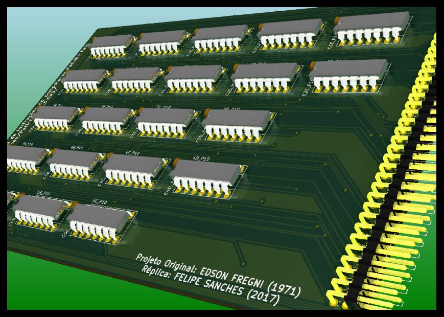
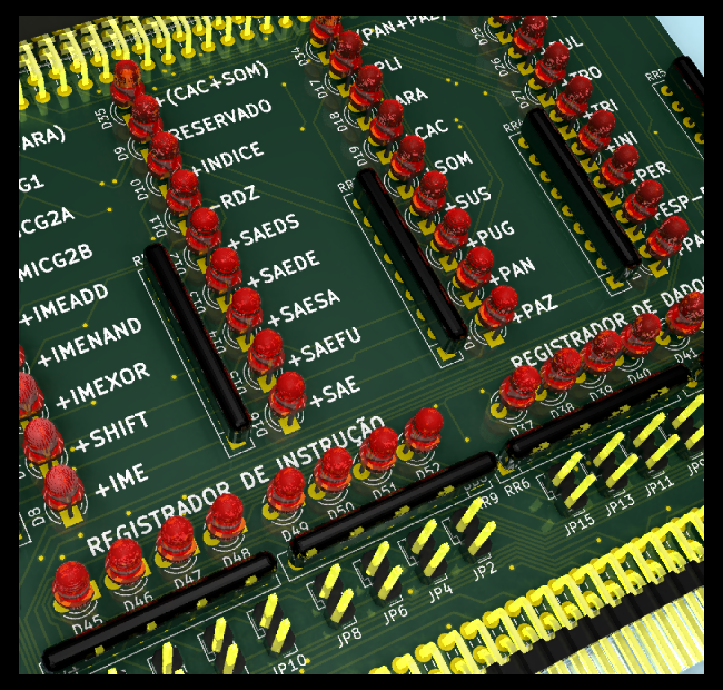
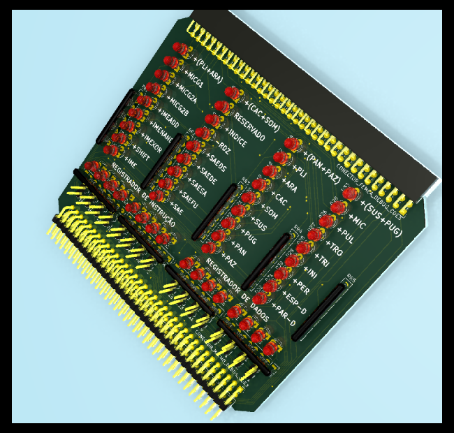
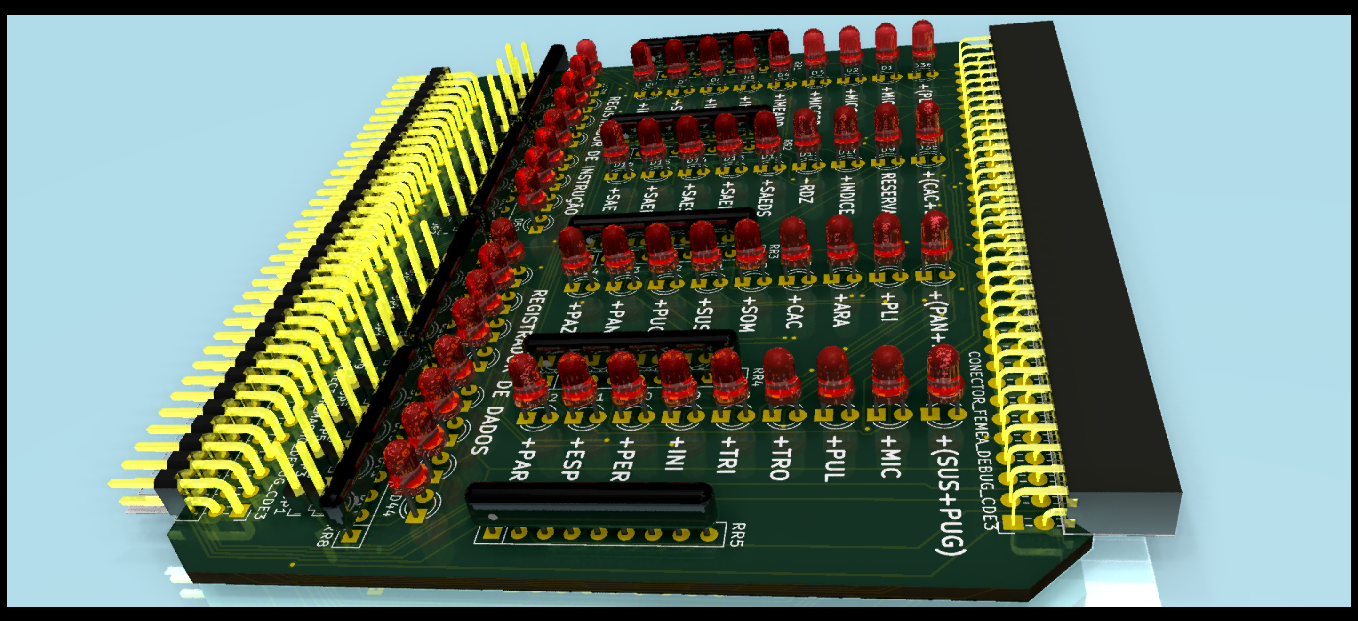
I bought red LEDs, buttons, and switches in the Santa Ifigênia neighborhood of São Paulo and added appropriate holes to the laser cutting schematic:

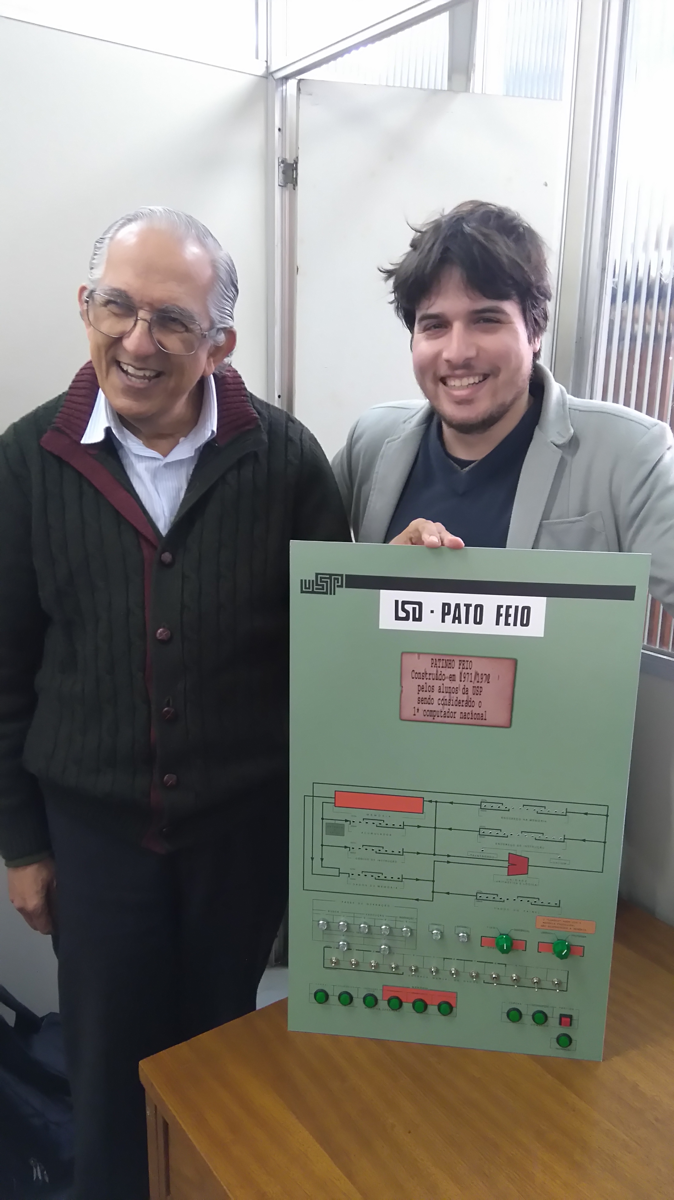
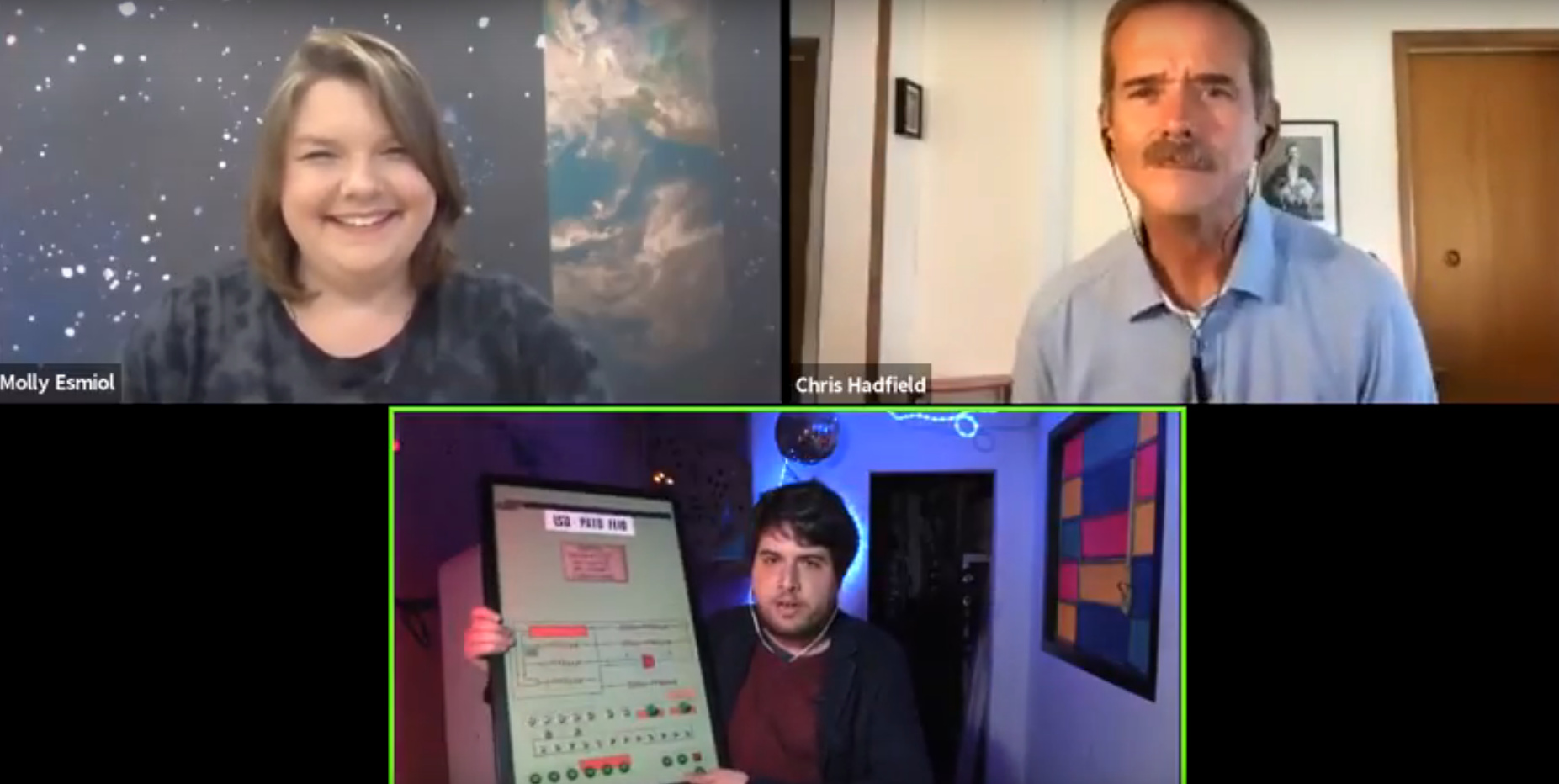
When I finished building the physical part of the front-panel replica, I took it for to Prof. JJNeto to see. It looks like he liked it:

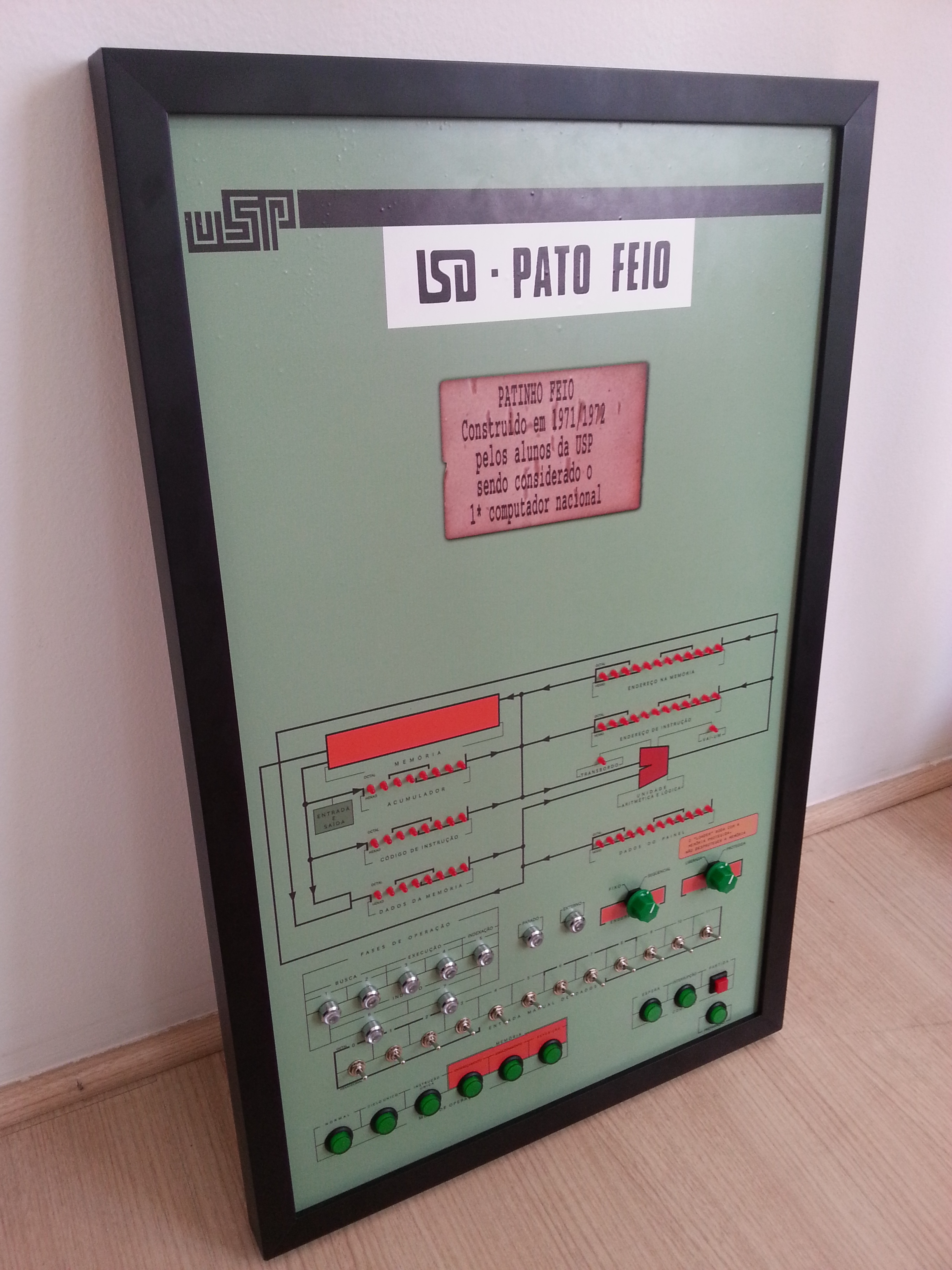
Then I added a black picture frame, and nowadays the panel looks like this:

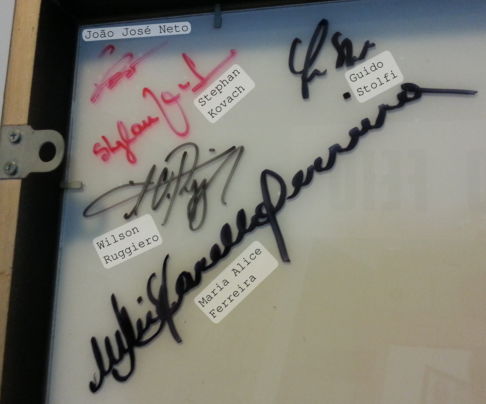
Over time, I’ve also been collecting autographs on the back of the panel from professors who were involved in the development of this project in the 1970s at USP:

In response to my original blog post about the discovery of the assembler manual, a friend added this comment:

Daniel Rosa Franzini
NOVEMBER 19, 2015 AT 9:47 AM
Juca,
In the the Electrical [Engineering] library there’s a section that nobody has ever looked at (except me). I remember that there’s a lot of good stuff there, including databooks, books, theses, and old bound documents in good or bad condition. I think it’s worth paying a visit. It’s way at the back (at least, it used to be), on the right side as you go in.
=> REPLY

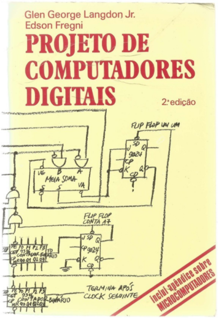
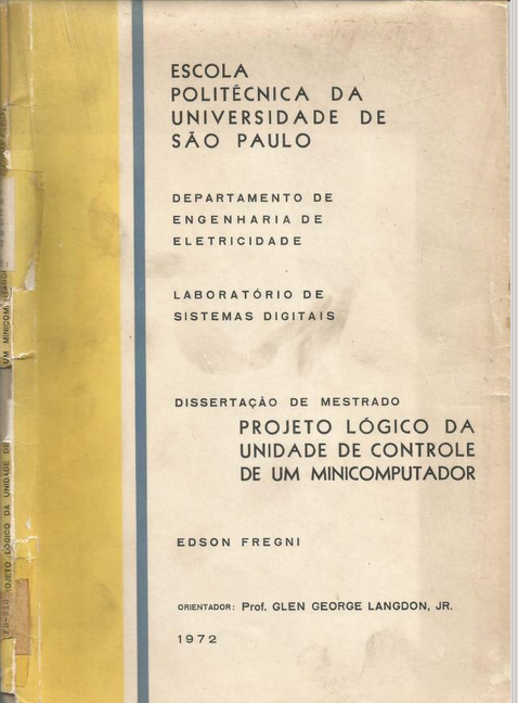
I can’t remember whether it was because of this, or not, that I set out on the next phase of this project. But I did, in fact, go to the library, and, with the help of Prof. JJNeto (who used his library card because mine had ceased to be valid when I left USP), took out some theses related to the subject. Over the course of the next few months, I gradually scanned in each of the master’s and doctor’s theses that had any connection to the Patinho Feio project. In all they numbered around 15 documents (I’m not sure of the exact number offhand). Each one has had its pages scanned in high resolution and pulished in individual repositories in my GitHub account, although the final PDFs were first grouped into a central repository here:

I’m currently also putting the PDFs up on the Internet Archive at:
https://archive.org/search.php?query=subject%3A"patinho+feio"

Well… I guess there’s already a LOT of information in this post. I hope you have fun digesting all of that! There’s a lot more to say, but it will be saved for future posts. My current goal is finishing the installation of the miniature panel wiring, and porting the MAME emulation code to run on an Arduino that controls the lights and reads the switches. Again, I’ll post more messages here as I continue making progress on this project.

Happy Hacking!
Felipe “Juca” Sanches

1 curtida

Translated into English by Seth Schoen on March 23, 2017.
Original posting in Brazilian Portuguese by Felipe Sanches on January 9, 2017.

CPU schematics

This project is broad enough to have a number of facets that are large projects in their own right. This has led me to study the subject a little bit at a time, navigating through the material as my curiosity leads me. One of these fronts is learning about the circuits that make up the computer’s CPU.

I first located the CPU’s electronic schematics in chapter 5 of the book “Projeto de Computadores Digitais” [Digital Computer Design] by Edson Fregni and Glen George Langdon Jr.

Professor Langdon Jr gave a graduate class in the 70s at the engineering school of the University of São Paulo (EPUSP) in his field of digital systems design, where he taught the students how to design a CPU. The best project of the class was what later got adopted as the design of the Patinho Feio CPU. And chapter 5 of the book is based in large part on the content of Professor Edson Fregni’s master’s thesis, which was advised by Prof. Langdon Jr.

The thesis, titled “Projeto Lógico da Unidade de Controle de um Minicomputador” [Logic Design of a Minicomputer Control Unit], EPUSP 1972, is available here.

During the last few days of my new year’s vacation I once again picked up an effort that I’d begun in June of the past year, transcribing these schematics into a digital format using the KICAD software:

This repo includes a PDF with a partial schematic. So far I’ve transcribed about 30% of the circuits. Some parts of the original schematics are harder to read, so I think this effort may help confirm that all the scanning was done well, or at least well enough to preserve the technical information in question. Also, having the circuits described digitally in a printed circuit board CAD application offers other interesting possibilities…

(…to be continued!)

Happy Hacking,
Felipe “Juca” Sanches

Translated into English by Seth Schoen on March 23, 2017.
Original posting in Brazilian Portuguese, by Felipe Sanches on January 12, 2017.


Today, reading a few passages from Prof. Edson Fregni’s master’s thesis, I noticed that there’s a citation to a document by Fregni himself, titled “Projeto Lógico do Primeiro Computador do LSD” [Logic Design of the First Computer of the Digital Systems Department], published in the Proceedings of the IV National Congress on Data Processing (SUCESU) in October 1971.


5.11 DOCUMENTATION
“Given the complexity of the system and the number of people involved with it, each phase the project was documented, from the very first meetings about the definition of the architecture, through the final steps like printed circuit ‘layouts,’ were recorded in special notebooks, computer listings, charts, etc.” (49) EDSON FREGNI

What attracted my attention about this citation was that the referenced work might contain especially important details about how the circuit was implemented in printed circuit boards:

In addition to the project documentation, like the micro-operations chart, control signal tree, etc., each circuit board is accompanied by the following basic documentation:

  1. Logic block diagram: a schematic diagram, like that of figure 4.12, illustrating the logic.
  2. Detailed diagram in terms of ICs, presenting the boards. These are drawings which include, in addition to logic information, descriptions of the connections made on each board, the position of the integrated circuits, signals on the connector pins, etc.
  3. Position of ICs on the board: this is a rather simple diagram which merely shows which are the ICs that should be placed in each of the standardized positions. This is a document prepared by the designer for the assembly teams’ use.

It would be fantastic to have access to item 4, in particular, as described below:

  1. “Layout” of the printed circuit: a schema showing the interconnections of the points on the printed circuit board. This is the basis for the prepartion of the final art which will be photographed and reproduced on the board.
  2. “Wire-wrap” listing: accompanies the boards assembled with this technique. They are prepared by a program run on the IBM 1130 system. They are used by the assembly team to carry out the connections on the board.
  3. List of signals in input and output connectors on the board: this is a simple report used later for preparing the board interconnection list.

Item 5 above could also be very useful if it were one day desired to plan a restoration of the original computer, which is currently being exhibited in the hallway of the Polytechnic administration building.

I didn’t manage to find the document in the USP libraries’ online search system, but it looks like there’s a copy in the IBGE library here in São Paulo:

http://biblioteca.ibge.gov.br/biblioteca-catalogo.html?view=detalhes&id=2271232

It’s a shame that there isn’t a downloadable PDF version. I’ll give them a call tomorrow and see if I can borrow it.

Quick update: I called today and the librarian is on vacation until Jan. 16.
I’ll try again next week…

Happy Hacking,
Felipe “Juca” Sanches

Translated into English by Seth Schoen on March 23, 2017.
Original posting in Brazilian Portuguese, by Felipe Sanches on January 23, 2017.

The copy isn’t available in the IBGE library in São Paulo, but there’s a chance that the library in Rio de Janeiro still has it in their collection. We’re going to check, and if the document is located, I was told that it can be sent to São Paulo as an interlibrary loan so I can take a look :slight_smile:

Translated into English by Seth Schoen on March 23, 2017.
Original posting in Brazilian Portuguese, by Felipe Sanches on February 4, 2017.

Images speak louder than words… :slight_smile:

Happy Hacking!
Felipe “Juca” Sanches

Translated into English by Seth Schoen on March 23, 2017.
Original posting in Brazilian Portuguese, by Felipe Sanches on February 9, 2017.

##[CDE-3] Instruction decoder board

The following are some 3D renders of the Patinho Feio computer’s boards that I’m redrawing in KiCad to start work on constructing a real (not emulated) replica.

This board is called CDE-3:

C: “Control”, as it’s one of several boards that implement the computer’s control unit.
DE: “Decoder”, as this board receives the 8 opcode bits (coming from the Instruction Register, RI) and 8 operand bits (coming from the Data Register, RD) drawn from the data flow.
3: means that this is the third board in the set of PCBs that make up the control unit.

Given the 16 opcode and operand bits, this board implements a boolean function for each CPU instruction. Therefore, the output signals indicate which is the current instruction coded by the 16 input bits.

##[CDE-3-DEBUG] Debugging board for the instruction decoder PCB

In order not to have to build the whole computer before being able to validate this board, I could have tested it with electronics benchtop test equipment. But instead I decided to design an auxiliary PCB (which I conveniently named CDE-3-DEBUG) which has LEDs for each of the output signals, with the names of those signals written in the silkscreen layer. I also added LEDs and jumpers with pull-up resistors for each of the 16 input bits. This way, it’s possible to manually enter a combination of bits on the input and visualize what result is computed by the CDE-3 board. Beyond helping with debugging, it also performs an educational role of interactively demonstrating how a CPU instruction decoder works.

The images below are 3D renders of the CDE-3-DEBUG board generated by KiCAD:

Although the CDE-3 board has a male 35x2 pin connector used to connect the board to the Patinho Feio backplane, I put 2 35x2 connectors on the CDE-3-DEBUG, one male and the other female. As a result, if all the DEBUG board’s jumpers are removed, it’s possible to set it in the middle of the path between the CDE-3 and the backplane. This way, if we operate the Patinho Feio as a whole in “single instruction” mode, it will be possible to visualize the instruction decoding signals on the LEDs during the computer’s normal operation.

Since this is a replica construction project, it makes more sense that the machine be left open with its “guts hanging out”. That is to say, instead of storing the boards inside a closed cabinet (as they were in the original machine), the most interesting aspect of this reproduction would be to attach them to a flat panel, hung up on a wall alongside extra boards like my CDE-3-DEBUG, to reveal the CPU’s internal signals. In this display configuration, new educational possibilities will arise to help teach the principles of computing and digital electronic design, which has been my main motivation to keep researching this computer in my free time.

Happy Hacking!
Felipe “Juca” Sanches

Translated into English by Seth Schoen on March 23, 2017.
Original postings in Brazilian Portuguese, by authors and dates denoted below (on February 2017).

Note: “Juca” is Felipe Sanches’ nickname.


[Feb 9, 2017] @kemelzaidan: Did you manage to get ahold of this document in the IBGE library?

[Feb 9, 2017] @FSanches: Unfortunately, I haven’t gotten any further reply on that. At some future point I’ll probably try to find the document again.

[Feb 12, 2017] @leofl: Phenomenal, Juca! Wouldn’t it be amazing to have students learning assembly language concepts using the Patinho Feio???

[Feb 12, 2017] @FSanches:
Yep. We already have some useful resources for that like the miniature replica of the Patinho Feio front panel, and also the emulator in MAME. But I think there are still a lot of educational opportunities to explore in this area. Not just for teaching assembly, but also dealing with the whole gamut of digital logic design issues, for example, and also basic principles of computation.

These days I’ve been dedicating a few hours a day to this project, in my free time, and so I’m overloaded with the huge quantity of historical documents that still need to be scanned and published on the Internet. In addition to this manual effort which is more substantial than what I’m equipped to do at the moment, there’s also a more sophisticated task which calls for even more time than simply scanning documents, and that’s actually reading all of them, interpreting all of them, digesting all of them. Then it would be possible to develop small educational activities surrounding this, making the material more palatable and accessible. This is to say that this enormous collection needs curation.

I’m thinking of maybe announcing a crowdfunding project to allow me to have more time to dedicate to this kind of work. I’ve also thought of the possibility of getting sponsorship from some company that may be interested in supporting this project. Apart from that, some of the angles that arise in this project will incur costs, like the price of electronic components and printed circuit prototyping services, in order to construct replicas like the CDE-3 board and the educational CDE-3-DEBUG which goes with it, as I explained in my last post.

Finally, I had a daydream about maybe recording a documentary on this subject.

Happy Hacking,
Felipe “Juca” Sanches

Translated into English by Seth Schoen on March 23, 2017.
Original posting in Brazilian Portuguese, by Felipe Sanches on February 17, 2017.

Today (Thursday, Feb. 16, 2017) I was very happy to have spoken in person with Prof. Edith Ranzini for the first time in her office at the Poli-USP. :slight_smile:

I could have told a ton of stories about the two or three hours of extended conversations that we had this morning, but, briefly, I’ve left just a single photo here of the two books that Prof. Edith presented me with today. I’ll read them gradually and maybe I’ll publish a few more images from these books here over the course of the next few days.

Happy Hacking,
Felipe “Juca” Sanches

Translated into English by Seth Schoen on March 23, 2017.
Original posting in Brazilian Portuguese, by Felipe Sanches on February 17, 2017.

Earlier today, Prof. Edith Ranzini showed me a ferrite core memory board which was used in the G10 computer. That was the same technology used for the Patinho Feio’s memory, but in the case of the G10, the memory was designed by Prof. Edith’s own team, while in the case of the Patinho Feio, a memory module fabricated by Philips (model FI 21) was used.

I didn’t manage to take photos of the professor’s memory module today, that was displayed in a wood-and-acrylic support. But a few months ago, I took photos of another copy of the same board which is part of Prof. Edison Spina’s personal collection. A surprising fact is that professor Spina had to save this board, because otherwise it was going to be discarded (thrown in the trash!)… Here are some photos (front and back) of the board:

On February 2017 I presented a lecture at the Polytechnic School of the University of São Paulo, being invited to do so by Professor Pedro Luiz Pizzigatti Corrêa. The lecture was offered as part of the Computational Systems Modeling and Simulation course for the students in the last year of the Computer Engineering undergraduate course at USP. The video below is a recording of the lecture in which I showcase details of the ongoing effort to gather, digitize and compile all documentation in existence related to the Patinho Feio computer. I’ve been working on this during the past few years. The lecture was offered in Brazilian Portuguese. There are English subtitles that were prepared by Seth Schoen but they are not yet available because I need to review them first. I’ll soon publish the subtitles as well, stay tuned!

This is, as far as I can tell, the oldest Brazilian “ASCII art”.
Even though the term was not used back then…

The image above was extracted from the Master’s thesis “O Patinho Feio como construção sociotécnica” (“The Patinho Feio [computer] as a socio-technical work”), published in 2003 by Marcia de Oliveira Cardoso of the Federal University of Rio de Janeiro. The thesis presents a very interesting account of the origins of this drawing:

According to professor João José Neto, a printer was also subsequently added as an I/O peripheral.
And new programs were written to enable the printing of data. The first printing, though, was a drawing
of a duckling. The drawing was crafted by the sister of Professor Selma Shimizu and it was digitized
by the Patinho Feio team [Figure 19]. According to Professor Antônio Massola, the amount
of time required to load this drawing into the computer memory was a whole night.

All of this process of building/adoption of the software lasted into the period following the official
inauguration date of the computer. Many of the solutions found during this development cycle
were actually devised after the inauguration. The project team disagrees on which of the peripherals
were already functional at the inauguration ceremony. There’s consensus, though, regarding the
fact that a program was loaded into the computer memory at this event. Regarding the duck drawing,
people are split on whether or not it was displayed on the inauguration ceremony. In case it was,
then it was not printed by the computer itself. Most people, on the other hand, believe that this
drawing was digitized after the initial formal inauguration event.

Based on the photo, I transcribed the artwork back into pure text (actual ASCII text this time!).
In case it may be useful, here’s a copy of the text content:

                 **     ******
                *    ***      ****
                *   *             *
            *******                 *
           *     *                   *
           *    *                     *
               *                       *
              *                   ***   *                          *
             *                   *   *  *                        ***
            *          ****     * ** *  *                       *  *
            *         *    *    * ** *  *                    ***  *
            *         *  ** *    ***** *                  ***    **
***         *          * ** *   ****   *                **    *** *
*  **        *          ****   *   ***********        **     *   *
*    **      *        ***    **              *       *          **
*       **    *      *   ****              **        *         * *
*          *   *     * **               ***         *        **  *
 *          *   *     ** *****     *****            *       *   *
  *          *   **     **    *****    *           *           *
  *           *    *      ***           *         *          **
  *            *    **       *          *         *   *    **
   *            *     **      **      **         *   *     ****
    *        *   *      *       * ****          *   *        *
     * *      *   *      *       *             *   *       **
        ***    *   *     *        *           *   *       *
           *    *   *    *         *        **   *         *
         **      *   *   *          ********    *          *
         *        *   * *                *     *         **  *
          *        *   **                    **          *  **
           **       ** *                                 **  *
             *        *                               *****   *
             **      *                                *      *
               **    *                      *   **  *      ** *
                 *****                       ***  **      *  **
                     *                                    *** *
                     *                                       *
                      *                                     *
                      *                                 ****
                       *                               *
                        *                            **
                         *                         **
                          ****                   ***
                              * **            ***
                                * ************ *
                               * *            * *
                              * *              * *
                             * *               * *
                           ** *                 * *
                          *   ****          ****  *
                          *       ***   ****      *
                           *        **  ***      *
                            *      *      *      *
                            * ******      *******
                             *                 *

Em 17/AGO/2018 eu tive a oportunidade de participar de uma sessão de perguntas para o astronauta canadense Chris Hadfield. A minha pergunta foi relacionada a paineis de controle de espaço-naves e eu usei o painel do Patinho Feio para exemplificar a minha pergunta.

Várias pessoas fizeram perguntas. A minha participação começa aos 41 minutos e 6 segundos do vídeo abaixo:

Thank you for the translations @FSanches! You might be interested in another forum, which recently mentioned this machine and your emulator:

2 curtidas

Last week I worked on installing all the wiring of the LEDs, switches and buttons in the panel:

1 curtida

Today I built a Centronics cable (PC paralel port cable) and I am trying to make the dot-matrix printer print… by receiving commands from the “hello world” program (that used to print “PATINHO FEIO\n” on the ASR33 Teletype).

I’ve made a YouTube live stream to celebrate the 50th anniversary of the inauguration of the Patinho Feio computer: